Pages

Wednesday, February 29, 2012

Ice protection - ELECTRICAL SYSTEM


want to read about : Ice protection - HOT AIR SYSTEM
ELECTRICAL SYSTEM
Fig. 13-5 Typical ice protection cyclic sequence
9. The  electrical  system  of  ice  protection  is generally used for turbo-propeller engine installa- tions, as this form of protection is necessary for the propellers.  The  surfaces  that  require  electrical heating are the air intake cowling of the engine, the  propeller blades and spinner and, when applicable,the oil cooler air intake cowling.
10. Electrical heating pads are bonded to the outer skin of the cowlings. They consist of strip conductors sandwiched between layers of neoprene, or glass cloth impregnated with epoxy resin.  To protect the pads against rain erosion, they are coated with a special, polyurethane-based paint. When the de- icing system is operating, some of the areas are con- tinuously heated to prevent an ice cap forming on the leading edges and also to limit the size of the ice that forms on the areas that are intermittently heated (fig.13-4).

Ice protection - HOT AIR SYSTEM


want to read about : Ice protection - INTRODUCTION
HOT AIR SYSTEM
Fig. 13-4 Electrical ice protection.
5. The hot air system provides surface heating of the engine and/or powerplant where ice is likely to form.  The  protection  of  rotor  blades  is  rarely necessary, because any ice accretions are dispersed by centrifugal action. If stators are fitted upstream of the first rotating compressor stage these may require protection. If the nose cone rotates it may not need anti-icing if its shape, construction and rotational characteristics  are  such  that  likely  icing  is acceptable.
6. The hot air for the anti-icing system is usually taken from the high pressure compressor stages. It is ducted through pressure regulating valves, to the parts requiring anti-icing. Spent air from the nose cowl anti-icing system may be exhausted into the compressor intake or vented overboard.

Ice protection - INTRODUCTION


INTRODUCTION
Ice protection
1. Icing of the engine and the leading edges of the intake duct can occur during flight through clouds containing  supercooled  water  droplets  or  during ground operation in freezing fog. Protection against ice formation may be required since icing of these regions can considerably restrict the airflow through the engine, causing a loss in performance and possible  malfunction  of  the  engine.  Additionally, damage may result from ice breaking away and being ingested into the engine or hitting the acoustic material lining the intake duct.
Fig. 13-1 Areas typically considered for ice protection.
2. An ice protection system must effectively prevent ice formation within the operational requirements of the particular aircraft. The system must be reliable, easy  to  maintain,  present  no  excessive  weight penalty  and  cause  no  serious  loss  in  engine performance when in operation.

Rolls-Royce advanced turbo-propeller | De Havilland H6 Gyron Junior


Rolls-Royce advanced turbo-propeller


De Havilland H6 Gyron Junior
When a change in government fighter require- ments halted development of the 20,000 lb thrust H4 Gyron in 1955, de Havilland decided to build a 0.45 scale version known as the H6 Gyron Junior. First run in August 1955 it was later used to power the Blackburn Buccaneer S1 at 7100 lb thrust and the stainless steel Bristol 188 at 14,000 lb with afterburner.

Monday, February 27, 2012

Controls and instrumentation - SYNCHRONIZING AND SYNCHROPHASING

want to read about :  Controls and instrumentation Electronic indicating systems

SYNCHRONIZING AND SYNCHROPHASING
58. Synchronizing and synchrophasing systems are  sometimes used on turbo-propeller engined aircraft to achieve a reduction of noise during flight.
59. On a multi-engined aircraft, a synchronizing system ensures the propeller speeds are all the same. This is achieved by an electrical system that compares  speed  signals  from  engine-mounted generators.  Out-of-balance  signals,  using  one engine  as  a  master  signal,  are  automatically corrected by electrically trimming the engine speeds until all signals are equal.

Controls and instrumentation Electronic indicating systems

want to read about :  Controls and instrumentation - Warning systems

Electronic indicating systems 
54. Electronic  indicating  systems  consolidate engine indications, systems monitoring, and crew alerting functions onto one or more cathode ray tubes (C.R.T.'s) mounted in the instrument panel. The information is displayed on the screen in the form of dials with digital readout and warnings, cautions and advisory messages shown as text.
Fig. 12-12 Typical electronic indicating display.
55. Only those parameters required by the crew to set  and  monitor  engine  thrust  are  permanently displayed on the screen.  The system monitors the remaining parameters and displays them only if one or more exceed safe limitations.  The pilot can, however, override the system and elect to have all main parameters in view at any time (fig. 12-12).

Controls and instrumentation - Warning systems

want to read about : Controls and instrumentation - Vibration
Warning systems
48. Warning  systems  are  provided  to  give  an indication of a possible failure or the existence of a dangerous condition, so that action can be taken to safeguard the engine or aircraft. Although the various systems of an aircraft engine are designed wherever possible to 'fail safe1, additional safety devices are sometimes  fitted.  Automatic  propeller  feathering should a power loss occur, and automatic closing of the high pressure fuel shut-off cock should a turbine shaft failure occur, are but two examples. On some engine types, the fuel system is fitted with a control  to enable the engine to be operated by manual throttling should a main fuel system failure occur.

49. In addition to a fire warning system (Part 14), a number of other audible or visual warning systems can be fitted to a gas turbine engine. These may be for low oil or fuel pressure, excessive vibration or overheating. Indication of these may be by warning light, bell or horn. A flashing light is used to attract the pilot's attention to a central warning panel (C.W.P.)

where the actual fault is indicated.

Controls and instrumentation - Vibration

want to read about :  Controls and instrumentation - Fuel flow

Vibration
44. A turbo-jet  engine  has  an  extremely  low vibration level and a change of vibration, due to an impending or partial failure, may pass without being noticed.  Many  engines  are  therefore  fitted  with vibration  indicators  that  continually  monitor  the vibration level of the engine. The indicator is usually a milli ammeter that receives signals through an amplifier from engine mounted transmitters (fig. 12- 11).
Fig. 12-11 Vibration transmitter andindicator.
45. A vibration transmitter is mounted on the engine casing and electrically connected to the amplifier and indicator. The vibration sensing element is usually an electro-magnetic transducer that converts the rate of vibration into electrical signals and these cause the indicator pointer to move proportional to the vibration level.  A warning lamp on the instrument panel is incorporated in the system to warn the pilot if an unacceptable  level  of  vibration  is  approached, enabling the engine to be shut down and so reduce the risk of damage.

46. The vibration level recorded on the gauge is the sum total of vibration felt at the pick-up.  A more accurate  method  differentiates  between  the frequency ranges of each rotating assembly and so enables the source of vibration to be isolated. This is particularly important on multi-spool engines.
47. A crystal-type vibration transmitter, giving a more  reliable  indication  of  vibration,  has  been developed for use on multi-spool engines. A system of filters in the electrical circuit to the gauge makes it possible to compare the vibration obtained against a known frequency range and so locate the vibration source. A multiple-selector switch enables the pilot to select a specific area to obtain a reading of the level of vibration.


Controls and instrumentation - Fuel flow

want to read about : Controls and instrumentation - Fuel temperature and pressure

Fuel flow

Fig. 12-10 Fuel flow transmitter andindicator.
43. Although the amount of fuel consumed during a given flight may vary slightly between engines of the same type, fuel flow does provide a useful indication of the satisfactory operation of the engine and of the amount of fuel being consumed during the flight. A typical system consists of a fuel flow transmitter, which is fitted into the low pressure fuel system, and an indicator, which shows the rate of fuel flow and the total fuel used in gallons, pounds or kilogrammes per hour (fig. 12-10). The transmitter measures the fuel flow electrically and an associated electronic unit gives a signal to the indicator proportional to the fuel flow.

Sunday, February 26, 2012

Controls and instrumentation - Fuel temperature and pressure

want to read about : Controls and instrumentation - Oil temperature and pressure

Fuel temperature and pressure
41. The  temperature  and  pressure  of  the  low pressure fuel supply are electrically transmitted to their respective indicators and these show if the low pressure system is providing an adequate supply of fuel without cavitation and at a temperature to suit the operating conditions.  The fuel temperature and pressure  indicators  are  similar  to  those  for temperature and pressure indication.
42. On some engines, a fuel differential pressure switch, fitted to the low pressure fuel filter, senses the pressure difference across the filter element.  The switch is connected to a warning lamp that provides indication of partial filter blockage, with the possibility of fuel starvation.


Controls and instrumentation - Oil temperature and pressure

want to read about : Controls and instrumentation - Turbine gas temperature


Oil temperature and pressure 


35. It is essential for correct and safe operation of the engine that accurate indication is obtained of both  the  temperature  and  pressure  of  the  oil.  Temperature  and  pressure  transmitters  and indicators are illustrated in fig 12-9.
Fig. 12-9 Oil temperature and pressure transmitters and indicators.
36. Oil temperature is sensed by a temperature- sensitive element fitted in the oil system. A change in temperature causes a change in the resistance value and, consequently, a corresponding change in the current flow at the indicator. The indicator pointer is deflected  by  an  amount  equivalent  to  the temperature change and this is recorded on the gauge in degrees centigrade.
37. Oil pressure is electrically transmitted to an indicator on the instrument panel. Some installations use  a  flag-type  indicator,  which  indicates  if  the pressure is high, normal or low; others use a dial- type gauge calibrated in pounds per square inch (p.s.i.).

Controls and instrumentation - Turbine gas temperature

want to read about :  Controls and instrumentation - Engine speed


Turbine gas temperature
27. The temperature of the exhaust gases is always indicated to ensure that the temperature of the turbine assembly can be checked at any specific operating condition. In addition, an automatic gas temperature control system is usually provided, to ensure that the maximum gas temperature is not exceeded (Part 10).
Fig. 12-7 Turbine thermocouple installation.
28. Turbine gas temperature (T.G.T.) sometimes referred to as exhaust gas temperature (E.G.T.) or jet pipe temperature (J.P.T.), is a critical variable of engine operation and it is essential to provide an indication of this temperature. Ideally, turbine entry temperature (T.E.T.) should be measured; however, because of the high temperatures involved this is not practical, but, as the temperature drop across the turbine varies in a known manner, the temperature at the outlet from the turbine is usually measured by suitably positioned thermocouples. The temperature may alternatively be measured at an intermediate stage of the turbine assembly, as shown in fig. 12-7.
29. The thermocouple probes used to transmit the temperature signal to the indicator consist of two wires of dissimilar metals that are joined together inside a metal guard tube. Transfer holes in the tube allow the exhaust gas to flow across the junction. The materials from which the thermocouples wires are made are usually nickel-chromium and nickel- aluminium alloys.
30. The probes are positioned in the gas stream so as to obtain a good average temperature reading and are normally connected to form a parallel circuit. An  indicator,  which  is  basically  a  millivoltmeter calibrated  to  read  in  degrees  centigrade,  is connected into the circuit (fig. 12-8).

Saturday, February 25, 2012

Rolls-Royce contra-rotating fan (concept) | Armstrong Siddeley Sapphire


Armstrong Siddeley Sapphire

        
Rolls-Royce contra-rotating fan (concept)
   The Sapphire originated in 1946 with the Metrovick F9, which was handed over to Armstrong-Siddeley when Metropolitan- Vickers withdrew from aviation in 1947. The Sapphire first ran in October 1948 and the engine was flight tested in Meteor, Hastings and Canberra aircraft; before going into production for the Gloster Javelin and Hawker Hunter F2.

Controls and instrumentation - Engine speed

want to read about :  Controls and instrumentation - Engine torque

Engine speed
21. All engines have their rotational speed (r.p.m.) indicated. On a twin or triple-spool engine, the high pressure assembly speed is always indicated; in most instances, additional indicators show the speed of  the  low  pressure  and  intermediate  pressure assemblies.
22. Engine  speed  indication  is  electrically ransmitted from a small generator, driven by the engine,  to  an  indicator  that  shows  the  actual evolutions per minute (r.p.m.), or a percentage of he maximum engine speed (fig. 12-5).
Fig. 12-5 Engine speed indicators andgenerator.
The engine speed is often used to assess engine thrust, but it does not give an absolute indication of the thrust being  produced  because  inlet  temperature  and  pressure conditions affect the thrust at a given engine speed.
23. The engine speed generator supplies a three- phase alternating current, the frequency of which is dependent upon engine speed. The generator output frequency  controls  the  speed  of  a  synchronous motor in the indicator, and rotation of a magnet assembly housed in a drum or drag cup induces movement of the drum and consequent movement of the indicator pointer,
24. Where  there  is  no  provision  for  driving  a generator, a variable-reluctance speed probe, in conjunction with a phonic wheel, may be used to induce an electric current that is amplified and then transmitted to an indicator (fig. 12-6).  This method can be used to provide an indication of r.p.m. without the need for a separately driven generator, with its associated  drives,  thus  reducing  the  number  of components and moving parts in the engine.

Friday, February 24, 2012

Controls and instrumentation - Engine torque

want to read about : Controls and instrumentation - Engine thrust

Engine torque
Fig. 12-4 A simple torquemeter system.
18. Engine torque is used to indicate the power that is developed by a turbo-propeller engine, and the indicator is known as a torquemeter.  The engine torque or turning moment is proportional to the horse-power and is transmitted through the propeller reduction gear.


19. A torquemeter system is shown in fig. 12-4. In this system, the axial thrust produced by the helical gears is opposed by oil pressure acting on a number of pistons; the pressure required to resist the axial thrust is transmitted to the indicator.

Controls and instrumentation - Engine thrust

want to read about : Controls and instrumentation - INSTRUMENTATION


  Engine thrust
10. The thrust of an engine is shown on a thrust- meter, which will be one of two basic types; the first measures turbine discharge or jet pipe pressure, and the second, known as an engine pressure ratio (E.P.R.) gauge, measures the ratio of two or three parameters. When E.P.R. is measured, the ratio is usually that of jet pipe pressure to compressor inlet pressure. However, on a fan engine the ratio may be  that of integrated turbine discharge and fan outlet pressures to compressor inlet pressure.
Fig. 12-3 Electro-mechanical E.P.R. transmitter.
11. In each instance, an indication of thrust output is given, although when only the turbine discharge pressure is measured, correction is necessary for variation of inlet pressure; however, both types may require  correction  for  variation  of  ambient  air temperature.  To  compensate  for  ambient atmospheric  conditions,  it  is  possible  to  set  a correction figure to a sub-scale on the gauge; thus, the minimum thrust output can be checked under all operating conditions.
12. Suitably  positioned  pilot  tubes  sense  the pressure or pressures appropriate to the type of indication being taken from the engine.  The pilot tubes are either directly connected to the indicator or to  a  pressure  transmitter  that  is  electrically connected to the indicator.
13. An  indicator  that  shows  only  the  turbine discharge pressure is basically a gauge, the dial of which may be marked in pounds per square inch (p.s.i.), inches of mercury (in. Hg.), or a percentage of the maximum thrust.

Controls and instrumentation - INSTRUMENTATION

want to read about :Controls and instrumentation - CONTROLS


INSTRUMENTATION
Fig. 12-2 Diagrammatic arrangement of engine control and instrumentation.
9. The performance of the engine and the operation of the engine systems are shown on gauges or by the operation of flag or dolls-eye type indicators. A diagrammatic arrangement of the control and instru- mentation for a turbo-jet engine is shown in fig. 12-2.


Controls and instrumentation - CONTROLS

want to read about :Controls and instrumentation - INTRODUCTION

 
CONTROLS
4. The control of a gas turbine engine generally requires the use of only one control lever and the monitoring of certain indicators located on the pilot's instrument panel (fig. 12-1). Operation of the control (throttle/power) lever selects a thrust level which is then maintained automatically by the fuel system (Part 10).
Fig. 12-1 Pilot's instrument panel - turbo-jet engines.

5. On engines fitted with afterburning, single lever control is maintained, although a further fuel system  is required to supply and control the fuel to the after burner (Part 16).

Controls and instrumentation - INTRODUCTION


INTRODUCTION
1. The  controls  of  the  gas  turbine  engine  are designed to remove, as far as possible, work load from the pilot while still allowing him ultimate control of the engine. To achieve this, the fuel flow is auto-matically controlled after the pilot has made the initial power selection (Part 10).
2. All engine parameters require monitoring and instrumentation is provided to inform the pilot of the correct functioning of the various engine systems and to warn of any impending failure. Should any of the automatic governors fail, the engine can be manually controlled by the pilot selecting the desired thrust setting and monitoring the instruments to maintain the engine within the relevant operating limitations.
3. The multitude of dials and gauges on the pilot's instrument panel may be replaced by one or a number of cathode ray tubes to display engine parameters.  These are small screens capable of displaying all of the information necessary to operate the engine safely.

Thursday, February 23, 2012

Starting and ignition - RELIGHTING


want to read about : Starting and ignition - IGNITION


RELIGHTING

Fig. 11-14 A typical flight relight envelope.


28. The jet engine requires facilities for relighting should the flame in the combustion system be extin- guished during flight. However, the ability of the engine to relight will vary according to the altitude and forward

Starting and ignition - IGNITION


want to read about : Starting and ignition - Hydraulic


IGNITION
18. High-energy (H.E.) ignition is used for starting all jet engines and a dual system is always fitted. Each system has an ignition unit connected to its own igniter plug, the two plugs being situated in different positions in the combustion system.
19. Each H.E. ignition unit receives a low voltage supply, controlled by the starting system electrical circuit,  from  the  aircraft  electrical  system.  The electrical energy is stored in the unit until, at a pre- determined value, the energy is dissipated as a high voltage, high amperage discharge across the igniter plug.
20. Ignition units are rated in 'joules' (one joule equals one watt per second). They are designed to give outputs which may vary according to require- ments.  A high value output (e.g. twelve joule) is necessary to ensure that the engine will obtain a sat- isfactory relight at high altitudes and is sometimes necessary for starting. However, under certain flight conditions, such as icing or take-off in heavy rain or snow, it may be necessary to have the ignition system continuously operating to give an automatic relight  should  flame  extinction  occur.  For  this condition, a low value output (e.g. three to six joule) is preferred because it results in a longer life of the igniter plug and ignition unit. Consequently, to suit all engine operating conditions, a combined system giving a high and low value output is favoured. Such a system would consist of one unit emitting a high output to one igniter plug, and a second unit giving a low output to a second igniter plug. However, some ignition units are capable o! supplying both high and  low  outputs,  the  value  being  pre-selected  asrequired.

21. An ignition unit may be supplied with direct current  (D.C.)  and  operated  by  a  trembler mechanism  or  a  transistor  chopper  circuit,  or supplied with alternating current (A.C.) and operated by a transformer. The operation of each type of unit is described in the subsequent paragraphs.

Fig. 11-10 A D.C. trembler-operated ignition unit.
22. The ignition unit shown in fig. 11-10 is atypical D.C.  trembler-operated  unit.  An  induction  coil, operated by the trembler mechanism, charges the reservoir  capacitor  (condenser)  through  a  high voltage rectifier. When the voltage in the capacitor is equal to the breakdown value of a sealed discharge gap, the energy is discharged across the face of the igniter plug. A choke is fitted to extend the duration of the discharge and a discharge resistor is fitted to ensure  that  any  residual  stored  energy  in  the capacitor is dissipated within one minute of the system being switched off. A safety resistor is fitted to enable the unit to operate safely, even when the high tension lead is disconnected and isolated.


23. Operation of the transistorized ignition unit is similar to that of the D.C. trembler-operated unit, except  that  the  trembler-unit  is  replaced  by  a transistor chopper circuit. A typical transistorized unit is  shown  in  fig.  11-11;

Starting and ignition - Hydraulic


want to read about : Starting and ignition - Gas turbine


Hydraulic
17. Hydraulic starting is used for starling some small jet engines. In most applications, one of the engine-mounted hydraulic pumps is utilized and is known as a pump/starter, although other applications may use a separate hydraulic motor. Methods of transmitting the torque to the engine may vary, but a typical system would include a reduction gear and clutch assembly. Power to rotate the pump/starter is provided by hydraulic pressure from a ground supply unit and is transmitted to the engine through the reduction gear and clutch.  The starting system is controlled by an electrical circuit that also operates hydraulic valves so that on completion of the starting  cycle  the  pump  /starter  functions  as  a  normalhydraulic pump.


Starting and ignition - Gas turbine


want to read about : Starting and ignition - Air
Gas turbine
14. A gas turbine starter is used for some jet engines and is completely self-contained. It has its own fuel and ignition system, starting system (usually electric or hydraulic) and self-contained oil system. This type of starter is economical to operate and provides a high power output for a comparatively low weight.
Fig. 11-9 A gas turbine starter.
15. The starter consists of a small, compact gas turbine engine, usually featuring a turbine-driven centrifugal compressor, a reverse flow combustion system and a mechanically independent |free-power turbine. The free-power turbine is connected to the main engine via a two-stage epicyclic reduction gear, automatic clutch and output shaft.  A typical gas turbine starter is shown in fig. 11-9.


16. On initiation of the starting cycle, the gas turbine

Starting and ignition - Air


want to read about : Starting and ignition - Iso-propyl-nitrate
Air
Fig. 11-6 An air starter motor.
9. Air starting is used on most commercial and some military jet engines. It has many advantages over other starting systems, and is comparatively light, simple and economical to operate. 10. An air starter motor transmits power through a reduction gear and clutch to the starter output shaft which is connected to the engine. A typical air starter motor is shown in fig. 11-6.


11. The starter turbine is rotated by air taken from an external ground supply, an auxiliary power unit (A.P.U.) or as a cross-feed from a running engine. The air supply to the starter is controlled by an elec- trically operated control and pressure reducing valve that is opened when an engine start is selected and is automatically closed at a predetermined starter speed. The clutch also automatically disengages as the engine accelerates up to idling r.p.m. and the rotation of the starter ceases. A typical air starting system is shown in fig. 11-7.

Starting and ignition - Iso-propyl-nitrate


want to read about : Starting and ignition - Cartridge


Iso-propyl-nitrate
Fig. 11-5 An iso-propyl-nitrate starting system.
8. This type of starter provides a high power output and gives rapid starting characteristics. It has a turbine that transmits power through a reduction gear to the engine. In this instance, the turbine is rotated by  high  pressure  gases  resulting  from  the combustion of iso-propyl-nitrate. This fuel is sprayed into a combustion chamber, which forms part of the starter, where it is electrically ignited by a high- energy ignition system. A pump supplies the fuel to the combustion chamber from a storage tank and an air pump scavenges the starter combustion chamber of fumes before each start. Operation of the fuel and air pumps, ignition systems, and cycle cancellation, is electrically controlled by relays and time switches. An iso-propyl-nitrate starting system is shown in fig.11-5.


Starting and ignition - Cartridge


want to read about Starting and ignition - Electric


Cartridge

Fig. 11-3 A low voltage electrical starting system.


7. Cartridge starting is sometimes used on military engines and provides a quick independent method of starting.

Starting and ignition - Electric

want to read about :Starting and ignition - INTRODUCTION

Electric


Fig. 11-2 An electric starter

5. The electric starter is usually a direct current (D.C.) electric motor coupled to the engine through a reduction gear and ratchet mechanism, or clutch, which automatically disengages after the engine has reached a self-sustaining speed (fig. 11-2).
6. The electrical supply may be of a high or low voltage and is passed through a system of relays and resistances to allow the full voltage to be progres- sively built up as the starter gains speed. It also provides the power for the operation of the ignition system.  The  electrical  supply  is  automatically cancelled when the starter load is reduced after the engine has satisfactorily started or when the time cycle  is  completed.  A typical  electrical  starting system is shown in fig. 11-3.


Starting and ignition - INTRODUCTION


INTRODUCTION

1. Two separate systems are required to ensure that a gas turbine engine will start satisfactorily. Firstly, provision must be made for the compressor and turbine to be rotated up to a speed at which adequate air passes into the combustion system to mix with fuel from the fuel spray nozzles (Part 10). Secondly, provision must be made for ignition of the air/fuel mixture in the combustion system. During engine starting the two systems must operate simul- taneously, yet it must also be possible to motor the engine over without ignition for maintenance checks and to operate only the ignition system for relighting during flight (para. 28).

2. The functioning of both systems is co-ordinated during a starting cycle and their operation is auto- matically controlled after the initiation of the cycle by an electrical circuit.  A typical sequence of events  during the start of a turbo-jet engine is shown in fig.11-1.

METHODS OF STARTING

Fig. 11-1 A typical starting sequence of a
turbo-jet engine.

Rolls-Royce RB211-535C | Metrovick G2

Rolls-Royce RB211-535C
Metrovick G2

Following the successful operation at sea of the Metrovick F2-based 2500 hp Gatric marine gas  turbine,  the  Royal  Navy  ordered  four larger sets with a maximum operational rating of 4500 shp. Developed from the Metrovick F2/4 Beryl axial-flow aircraft engine; the G2s were installed in the Motor Gunboats 'Bold Pioneer1  and  'Bold  Pathfinder; the  former going to sea in 1951.


HYDRAULIC FLUID PROJECTS

HYDRAULIC  FLUID
 
                 Hydraulic  system  liquids  are  used  primarily  to  transmit  and  distribute  forces  to  various  units  to  be  actuated. Liquids  are  able  to  do  this  because  they  are  almost  incompressible. Pascal’s  Law  states  that  pressure  applied  to  any  part  of  a  confined  liquid  is  transmitted  with  undiminished  intensity  to  every  other  part. Thus  if  a  number  of  passages  exist  in  a  system  pressure  can  be  distributed  through  all  of  them  by  means  of  the  liquid.

                  Manufactures  of  hydraulic  devices  usually  specify  the  type  of  liquid  best  suited  for  use  with  their  equipment, in  view  of  the  working  conditions, the  service  required, temperature  expected  inside  and  outside  the  systems, pressure  the  liquid  must  withstand, the  possibilities  of  corrosion  and  other  conditions  that  must  be  considered. Some  of  the  properties  and  characteristics  that  must  be  considered  when  selecting  a  satisfactory  liquid  for  a  particular  system  are  discussed  below. 

AIRCRAFT HYDRAULIC SYSTEMS PROJECTS


AIRCRAFT  HYDRAULIC  SYSTEMS

                    The  word  hydraulic  is  based  on  the  Greek  word  for  water, and  originally  meant  the  study  of  the  physical  behavior  of  water  rest  and  in  motion. Today  the  meaning has  been  expanded  to  include  the  physical  behavior  of  all  liquids, including  hydraulic  fluid.
 
                     It  has  a  great  role  in  aviation. Early aircrafts  has  hydraulic  brake  system. As  aircraft  became  more  sophisticated  newer  systems  with  hydraulic  power  were  developed.
  
                     Landing  gear, wing  flaps, speed  and  wheel  brake, and  flight  control  surfaces  are  the  different  parts  commonly  operated  by  hydraulic  systems.

Wednesday, February 22, 2012

FUEL HEATING


96. The spill spray nozzle system, however, involves a somewhat modified type of fuel supply and control system from that used with the previous types. A means has to be provided for removing the


spill and also for controlling the amount of spill flow at various engine operating conditions. A
disadvatage of this system is that excess heat may be generated when a large volume of fuel is being recirculated to inlet. Such heat may eventually leadto a deterioration of the fuel.

FUEL HEATING


FUEL HEATING

100. On many engines, a fuel-cooled oil cooler (Part 8) is located between the L.P. fuel pump and the inlet to the fuel filter (fig. 10-13), and advantage is taken of this to transfer the heat from the oil to the fuel and thus prevent blockage of the filter element by ice particles. When heat transference by this means is insufficient, the fuel is passed through a second heat exchanger where it absorbs heat from a thermostatically controlled airflow taken from the compressor.
EFFECT OF A CHANGE OF FUEL
101. The main effect on the engine of a change from one grade of fuel to another arises from the variation of specific gravity and the number of heat units obtainable from a gallon of fuel. As the number of heat units per pound is practically the same for all fuels approved for gas turbine engines, a comparison of heat values per gallon can be obtained by comparing specific gravities.  

Fuel requirements


Fuel requirements

107. In general, a gas turbine fuel should have the following qualities:

(1)  Be 'pumpable' and flow easily under all operating conditions.
(2) Permit engine starting at all ground  conditions and give satisfactory flight relighting characteristics.
(3)  Give efficient combustion at all conditions.
(4)  Have as high a calorific value as possible.
(5)  Produce minimal harmful effects on the combustion system or the turbine blades.
(6)  Produce minimal corrosive effects on the fuel system components.
(7) Provide adequate lubrication for the moving parts of the fuel system.
(8)  Reduce fire hazards to a minimum.

108. The pumping qualities of the fuel depend upon its viscosity or thickness, which is related to fuel temperature, Fuel must be satisfactory down to approximately -50 deg. C. As the fuel temperature falls, ice crystals may form to cause blockage of the fuel filter or the orifices in the fuel system. Fuel heating and anti-icing additives are available to alleviate this problem.

Vapour locking and boiling | Fuel contamination control


Vapour locking and boiling

113. The main physical difference between kerosine and wide-cut fuels is their degree of volatility, the latter type of fuel having a higher volatility, thus increasing the problem of vapour locking and boiling. With kerosine-type fuels, the volatility is controlled by distil-lation and flash point, but with the wide-cut fuels it is controlled by distillation and the Reid Vapour Pressure (R.V.P.) test. In this test, the absolute pressure of the fuel is recorded by special apparatus with the fuel temperature at 37.8 deg. C. (100 deg. F.)

114. Kerosine has a low vapour pressure and will boil only at extremely high altitudes or high tempera-tures, whereas a wide-cut fuel wilt boil at a much lower altitude.

FUEL SPRAY NOZZLES


FUEL SPRAY NOZZLES
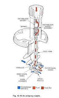
89. The final components of the fuel system are the fuel spray nozzles, which have as their essential function the task of atomizing or vaporizing the fuel to ensure its rapid burning. The difficulties involved in this process can be readily appreciated when one considers the velocity of the air stream from the compressor and the short length of combustion system (Part 4) in which the burning must be completed.

LOW PRESSURE FUEL SYSTEM

LOW PRESSURE FUEL SYSTEM


83. An L.P. system (fig.10-13) must be provided to supply the fuel to the engine at a suitable pressure, rate of flow and temperature, to ensure satisfactory engine operation. This system may include an L.P. pump to prevent vapour locking and cavitation of the fuel, and a fuel heater to prevent ice crystals forming. A fuel filter is always used in the system and in some instances the flow passes through an oil cooler (Part8). Transmitters may also be used to signal fuel pressure, flow and temperature (Part 12).

FUEL PUMPS


84. There are two basic types of fuel pump, the plunger-type pump and the constant-delivery gear-type pump; both of these are positive displacement pumps. Where low pressures are required at the fuel spray nozzles, the gear-type pump is preferred because of its lightness.

ELECTRONIC ENGINE CONTROL


ELECTRONIC ENGINE CONTROL

77. As stated in para. 8, some engines utilize a system of electronic control to monitor engine performance and make necessary control inputs to maintain certain engine parameters within predeter- mined limits. The main areas of control are engine shaft speeds and exhaust gas temperature (E.G.T.) which are continuously monitored during engine operation. Some types of electronic control function as a limiter only, that is, should engine shaft speed or E.G.T. approach the limits of safe operation, then an  input is made to the fuel flow regulator (F.F.R.) to reduce the fuel flow thus maintaining shaft speed or E.G.T. at a safe level. Supervisory control systems may contain a limiter function but, basically, by using aircraft generated data, the system enables a more appropriate thrust setting to be selected quickly and accurately by the pilot. The control system then  makes small control adjustments to maintain engine thrust consistent with that pre-set by the pilot, regardless of changing atmospheric conditions. Full authority digital engine control (FAD.E.G.) takes over virtually all of the steady state and transient control intelligence and replaces most of the hydromechani-cal and pneumatic elements of the fuel system. The  fuel system is thus reduced to a pump and control valve, an independent shut-off cock and a minimum of additional features necessary to keep the engine safe in the event of extensive electronic failure.

78. Full authority fuel control (F.A.F.C.) provides full electronic control of the engine fuel system in the sameway as F.A.D.E.C., but has none of the transient control intelligence capability used to control the  compressor airflow system as the existing engine control system is used for these

Friday, February 3, 2012

A proportional flow control system.

Fig. 10-7  A proportional flow control system.

23. H.P. compressor shaft r.p.m. is governed by a hydro-mechanical governor which uses hydraulic pressure proportional to engine speed as its controlling parameter. A rotating spill valve senses the engine speed and the controlling pressure is used to limit the pump stroke and so prevent over-speeding of the H.P. shaft rotating assembly. The controlling pressure is unaffected by changes in fuelspecific gravity.
24. At low H.P. shaft speeds, the rotating spill valve is held open, but as engine speed increases, centrifugal loading moves the valve towards the closed position against the diaphragm loads. This restricts the bleed of fuel to the L.P. side of the valve until, at governed speed, the governor pressure deflects the servo control diaphragm and opens the servo spill valve to control the fuel flow and thereby the H.P. shaft speed. 
25. If the engine gas temperature attempts to exceed the maximum limitation, the current in the L.P. speed limiter and temperature control solenoid is reduced. This opens the spill valve to reduce the pressure on the pressure drop control diaphragm. The flow control spill valve then opens to reduce the pump servo pressure and fuel pump output.
26. To prevent the L.P. compressor from over-speeding, multi-spool engines usually have an L.P. compressor shaft speed governor. A signal of L.P. shaft speed and intake temperature is fed to an amplifier and solenoid valve, the valve limiting the fuel flow in the same way as the gas temperature control (para. 25).
27. The system described uses main and starting spray nozzles under the control of an H.P. shut-off valve. Two starting nozzles are fitted in the combustion chamber, each being forward of an igniter plug. When the engine has started, the fuel flow to these nozzles is cut off by the H.P. shut-off valve.
28. To ensure that a satisfactory fuel pressure to the spray nozzles is maintained at high altitudes, a back pressure valve, located downstream of the throttle valve, raises the pressure levels sufficiently to ensure satisfactory operation of the fuel