Showing posts with label A turbo/ram jet engine.. Show all posts

Monday, January 23, 2012

Ring seals


Ring seals

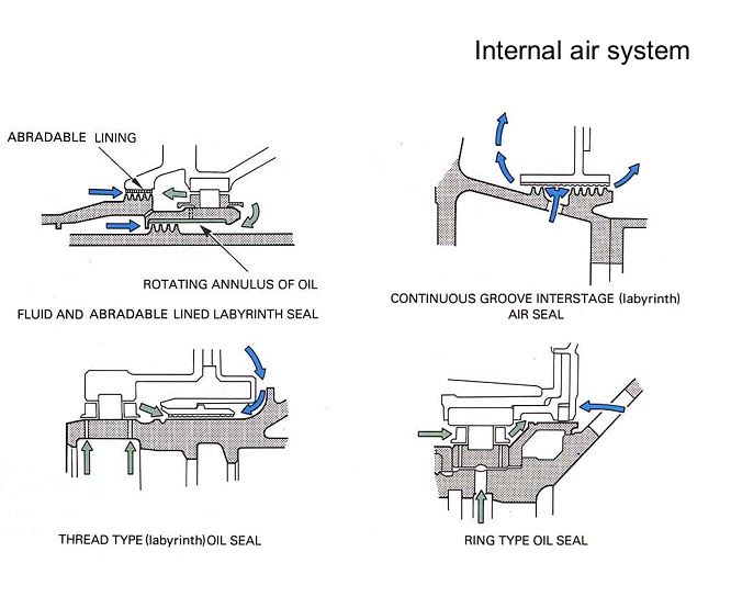
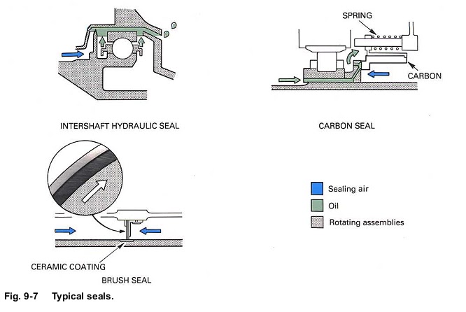
17. A ring seal (fig. 9-7) comprises a metal ring which is housed in a close fitting groove in the static housing. The normal running clearance between the ring and rotating shaft is smaller than that which can be obtained with the labyrinth seal. This is because the ring is allowed to move in its housing whenever the shaft comes into contact with it.
18. Ring seals are used for bearing chamber sealing, except in the hot areas where oil degradation due to heat would lead to ring seizure within its housing.

Hydraulic seals

19. This method of sealing is often used between two rotating members to sea a bearing chamber.
Unlike the labyrinth or ring seal, it does not allow a controlled flow of air to traverse across the seal,

20. Hydraulic seals (fig. 9-7) are formed by a seal fin immersed in an annulus of oil which has been created by centrifugal forces. Any difference in air pressure inside and outside of the bearing chamber is compensated by a difference in oil level either side of the fin.
Carbon seals

21. Carbon seals (fig. 9-7) consist of a static ring of carbon which constantly rubs against a collar on a rotating shaft. Several springs are used to maintain contact between the carbon and the collar. This type of seal relies upon a high degree of contact and does not allow oil or air leakage across it. The heat caused by friction is dissipated by the oil system.

Brush seals

Saturday, January 7, 2012

Rolls-Royce Turbomeca Adour Mk102 | Rolls-Royce RB37 Derwent V


Rolls-Royce RB37 Derwent V
Rolls-Royce Turbomeca Adour Mk102
Work commenced in January 1945 on a 0.855 scale Nene, reduced to fit the engine nacelle of a Gloster Meteor. Known as the Derwent V the engine passed a 100 hr test at 2600 lb thrust in June 1945 and in September went into production with a service rating of 3500 lb. Two world speed records were set by Meteor IV’s powered by special Derwent V’s in November 1945 and September 1946.

COMBUSTION CHAMBER PERFORMANCE

Fig. 4-9 Annular combustion chamber.
COMBUSTION CHAMBER PERFORMANCE
23. A combustion chamber must be capable of allowing fuel to burn efficiently over a wide range of operating conditions without incurring a large pressure loss. In addition, if flame extinction occurs, then it must be possible to relight. In performing these functions, the flame tube and spray nozzleatomizer components must be mechanically reliable.
24. The gas turbine engine operates on a constant pressure cycle, therefore any loss of pressure during the process of combustion must be kept to a minimum. In providing adequate turbulence and mixing, a total pressure loss varying from about 3 to 8 per cent of the air pressure at entry to the chamber is incurred.


Sunday, December 11, 2011

A turbo-rocket engine.

Fig. 1-12 A turbo-rocket engine.
20. The turbo-rocket engine (fig. 1-12) could be considered as an alternative engine to the turbo/ram jet; however, it has one major difference in that it carries its own oxygen to provide combustion,
21. The engine has a low pressure compressor driven by a multi-stage turbine; the power to drive the turbine is derived from combustion of kerosine and liquid oxygen in a rocket-type combustion chamber. Since the gas temperature will be in the order of 3,500 deg. C, additional fuel is sprayed into the combustion chamber for cooling purposes before the gas enters the turbine. This fuel-rich mixture (gas) is then diluted with air from the compressor and the surplus fuel burnt in a conventional afterburning system.
22. Although the engine is smaller and lighter than the turbo/ram jet, it has a higher fuel consumption. This tends to make it more suitable for an interceptor or space-launcher type of aircraft that requires high speed, high altitude performance and normally has a flight plan that is entirely accelerative and of short duration.

Saturday, December 10, 2011

A turbo/ram jet engine.

Fig. 1-10 Comparative propulsive efficiencies
16. At aircraft speeds below approximately 450 miles per hour, the pure jet engine is less efficient than a propeller-type engine, since its propulsive efficiency depends largely on its forward speed; the pure turbo-jet engine is, therefore, most suitable for high forward speeds. The propeller efficiency does, however, decrease rapidly above 350 miles per hour due to the disturbance of the airflow caused by the high blade-tip speeds of the propeller. These characteristics have led to some departure from the use of pure turbo-jet propulsion where aircraft operate at medium speeds by the introduction of a combination of propeller and gas turbine engine.
17. The advantages of the propeller/turbine combination have to some extent been offset by the introduction of the by-pass, ducted fan and propfan engines. These engines deal with larger comparative airflows and lower jet velocities than the pure jet engine, thus giving a propulsive efficiency (Part 21) which is comparable to that of the turbo-prop and exceeds that of the pure jet engine (fig. 1-10).