Showing posts with label X-Gliders. Show all posts

Thursday, October 27, 2011

How To Make Traditional Boomerangs


Construction of traditional Australian boomerang (for right hand)
Instructions how to make traditional boomerang
1. Take plywood sheet of 12mm thickness. Draw boomerang contour pattern as shown in picture above. The 107 degree angle size is not critical, just optimum. It can be more or less than 107deg. Chord length near the center of boomerang = 80 mm, and 60 mm near tips. Make wing chord length few millimeters wider as is required, because it necessarily reduces during sanding process. Also make some access length at boomerang wings tips, as it possible, that you will have to cut them during tune procedure of the boomerang.
Note:
If you make angle >>107, consider that rotation plate becomes small and it can be difficult to keep the
boomerang spinning.
If you make angle of about 90 degrees, the boomerang flight trajectory circle radius is minimum. Angles
<90 deg and >90 degrees increase circle radius.
2. First what you have to do is to sand dihedrals of wings. You have to make decision were is top and
bottom. Put plywood boomerang on flat table and see if the tips are up or down. The traditional Australian boomerang has positive dihedral. The best choice is to find position in which the boomerang wings tips are up. (Do not care about that if your plywood is absolutely flat).
Remove some material from boomerang bottom at distance of about D=70...90 mm from both tips. It can
be asymmetrical, but condition A+B = 14 mm should be satisfied.
Note:

Tuesday, October 25, 2011

The Clark Y Airfoil is Ideal for RC Model Aircraft

Complete instructions on how to plot out a Clark Y airfoil Outline of a Clark Y airfoil

Clark Y is the name of an airfoil that is widely used in aircraft design. With its predictable and gentle stall characteristics and flat bottom outline, the Clark Y airfoil is an ideal choice for sport RC model aircraft. I have used the Clark Y airfoil for all my model airplane designs, from the Electro Aviator to the Finch.

See later on in this article for complete instructions on how to plot out a Clark Y airfoil from tabulated ordinates. Drawing up your own airfoil shape is very easy to do. You can use the tabulated ordinate method to draw a Clark Y airfoil by hand, or use TurboCAD for the drafting task. You can then use TurboCAD to draw additional versions of the finished Clark Y wing rib shape for any length wing rib your model aircraft design requires.
Table 1: Ordinates to draw a Clark Y airfoil. All figures are a percentage of rib chord (top line), with percentage of chord upper and lower airfoil points on next two lines

Chickadee Fuselade Plan Side View,

Tips On Trimming and Flying a Catapult Glider

Now that there are two new indoor catapult glider classes, and there is still an outdoor catapult class, you guys can't use the excuse that your arm isn't any good anymore! Now all you need to do is pick up your old broken Wakefield, or Bostonian motors, and make a little loop for your catapult (1/4" dowel works nicely) and tie it on, pick up your glider, pull back, and let go! No more running twenty-five yards, lunging and throwing your arm out of its socket all day long, then complaining you're not getting any height. No, now all you need to do is add another loop of 1/4" tan II and let fly!

Keep in mind, many of these tips will also apply directly to a hand launch glider, in fact that's where many of them came from. So if there are any other brave souls that have caught the age old, highly contagious, HLG disease, keep your ears open.

Saturday, September 3, 2011

X-Gliders: Exploring Flight Research with Experimental Gliders

Objectives  

  1. The students will:
  2. Build a glider.
  3. Learn how to change the flight characteristics of a glider.
  4. Conduct an experiment to answer a question.

Standards and Skills

Science
Science as Inquiry
Physical Science
Science and Technology
Mathematics
Measurement
Problem Solving
Science Process Skills
Making Models
Investigating
Predicting

Background Information
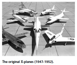
A look at the research aircraft flown by NASA and its predecessor, the National Advisory Committee for Aeronautics (NACA), since the 1940’s reveals an evolution of wing designs. In fact, each of the first series of NACA experimental research aircraft (“X-planes”) used different wing and tail configurations to tackle the problems of supersonic flight. These early jet aircraft had straight wings (X-1), wings that angled (swept) toward the tail (X-2), triangular (delta) wings (XF-92), and wings that could be moved in flight to change the angle of backward sweep (X-5). Each design added to our knowledge of high-speed flight.

More recently, aircraft designs have incorporated wings that sweep forward (X-29), and even wings that sweep forward and backward at the same time (AD-1 oblique wing aircraft). The X-29 and X-31 also made use of small wing-like control surfaces called canards which are located ahead of the main wings. The X-36, which was flown during the late 1990’s, used canards and swept-back wings but had no vertical tail. (For additional background information see the Aircraft as Research Tools page at the end of this Educational Brief.)