Showing posts with label A pulse jet engine. Show all posts

Thursday, June 7, 2012

Rolls-Royce RB168 MK807 | Blackburn Nimbus


Rolls-Royce RB168 MK807
Blackburn Nimbus

 The Nimbus was developed from the A129 turbo-shaft which, in its turn, was a modified Turbomeca Artouste built under licence. The Nimbus developed 968 hp, but for helicopter use was flat-rated at 710 hp. The engine was used in Westland Wasp and Scout helicopters and four 700 hp units were used to power the experimental 5RN-2 hovercraft.

Tuesday, May 1, 2012

Rolls-Royce Turbomeca Adour MK151 | Napier Gazelle

Rolls-Royce Turbomeca Adour MK151
Napier Gazelle
Rolls-Royce Turbomeca Adour MK151 The Gazelle turbo-shaft engine first ran in December 1955 at 1260 shp, a figure later increased to 1610 shp on production engines. Gazelles were used to power Bristol Belvedere and Westland Wessex helicopters. Gazelle production was taken over by Rolls- Royce in 1961.

Monday, January 30, 2012

Rolls-Royce Gem 60 | Rolls-Royce AJ65 Avon


Rolls-Royce Gem 60

Rolls-Royce AJ65 Avon
Work commenced early in 1945 on the AJ65 axial flow turbo-jet with a design thrust of 6500 lb. This figure was reached in 1951 with the 100 series RA3. In 1953 the considerably redesigned 200 series RA14 was type tested at 9500 lb thrust. Development culminated in the 300 series RB146 which produced 17.110lb thrust with afterburning

Monday, January 23, 2012

Ring seals


Ring seals

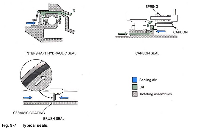
17. A ring seal (fig. 9-7) comprises a metal ring which is housed in a close fitting groove in the static housing. The normal running clearance between the ring and rotating shaft is smaller than that which can be obtained with the labyrinth seal. This is because the ring is allowed to move in its housing whenever the shaft comes into contact with it.
18. Ring seals are used for bearing chamber sealing, except in the hot areas where oil degradation due to heat would lead to ring seizure within its housing.

Hydraulic seals

19. This method of sealing is often used between two rotating members to sea a bearing chamber.
Unlike the labyrinth or ring seal, it does not allow a controlled flow of air to traverse across the seal,

20. Hydraulic seals (fig. 9-7) are formed by a seal fin immersed in an annulus of oil which has been created by centrifugal forces. Any difference in air pressure inside and outside of the bearing chamber is compensated by a difference in oil level either side of the fin.

Carbon seals

21. Carbon seals (fig. 9-7) consist of a static ring of carbon which constantly rubs against a collar on a rotating shaft. Several springs are used to maintain contact between the carbon and the collar. This type of seal relies upon a high degree of contact and does not allow oil or air leakage across it. The heat caused by friction is dissipated by the oil system.

Brush seals

Sunday, January 15, 2012

An oil tank,OIL SYSTEM COMPONENTS


OIL SYSTEM COMPONENTS :


12. The oil tank (fig. 8-4) is usually mounted on the engine and is normally a separate unit although it
may also be an integral part of the external gearbox. It must have provision to allow the lubrication system
to be drained and replenished. A sight glass or a system contents to be checked. The filler can be
Fig. 8-4 An oil tank.
either the gravity or pressure filling type; on some engines both types are fitted. Provision is also made
for a continuous supply of oil to be made available in aircraft which are designed to operate during
inverted flight conditions. Since air is mixed with the oil in the bearing chambers, a de-aerating device is
incorporated within the oil tank which removes the air from the returning oil.