Showing posts with label A ram Jet engine. Show all posts

Monday, January 30, 2012

Rolls-Royce Gem 60 | Rolls-Royce AJ65 Avon


Rolls-Royce Gem 60

Rolls-Royce AJ65 Avon
Work commenced early in 1945 on the AJ65 axial flow turbo-jet with a design thrust of 6500 lb. This figure was reached in 1951 with the 100 series RA3. In 1953 the considerably redesigned 200 series RA14 was type tested at 9500 lb thrust. Development culminated in the 300 series RB146 which produced 17.110lb thrust with afterburning

Thursday, January 12, 2012

A pressure relief valve type oil system,Pressure relief valve system,INTRODUCTION,Lubrication

Lubrication :


INTRODUCTION :
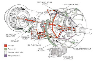
Fig. 8-1 A pressure relief valve type oil system.

1. The lubrication system is required to provide lubrication and cooling for all gears, bearings and
splines. It must also be capable of collecting foreign matter which, if left in a bearing housing or gearbox,
can cause rapid failure. Additionally, the oil must protect the lubricated components which are manu-
fractured from non-corrosion resistant materials. The oil must accomplish these tasks without significant
deterioration.


2. The requirements of a turbo-propeller engine are somewhat different to any other types of aero gas
turbine. This is due to the additional lubrication of the heavily loaded propeller reduction gears and the
need for a high pressure oil supply to operate the propeller pitch control mechanism.

3. Most gas turbine engines use a self-contained re circulatory lubrication system in which the oil is
distributed around the engine and returned to the oil tank by pumps. However, some engines use a
system known as the total loss or expendable system in which the oil is spilled overboard after the engine
has been lubricated.

LUBRICATING SYSTEMS

An internal gearbox,Direct drive

Fig. 7-3 An internal gearbox.


Direct drive
11. In some early engines, a radial driveshaft was used to drive each, or in some instances a pair, of
accessory units. Although this allowed each accessory unit to be located in any desirable location
around the engine and decreased the power transmitted through individual gears, it necessitated
a large internal gearbox. Additionally, numerous radial driveshafts had to be incorporated within the
design. This led to an excessive amount of time required for disassembly and assembly of the engine
for maintenance purposes.

Mechanical arrangement of internal gearboxes.


6
. To minimize unwanted movement between the compressor shaft bevel gear and radial driveshaft
(fig. 7-1)
bevel gear, caused by axial movement of the compressor shaft, the drive is taken by one of three basic methods (fig. 7-2). The least number of components is used when the compressor shaft bevel gear is mounted as close to the compressor shaft location bearing as possible, but a small amount of movement has to be accommodated within the meshing of the bevel gears. Alternatively, the compressor shaft bevel gear may be mounted on a stub shaft which has its own location bearing. The stub shaft is splined onto the compressor shaft which allows axial movement without affecting the bevel gear mesh. A more complex system utilizes an idler gear which meshes with the compressor shaft via straight spur gears, accommodating the axial movement, and drives the radial driveshaft via a bevel gear arrangement. The latter method was widely employed on early engines to overcome gear engagement difficulties at high speed.


Saturday, January 7, 2012

EXHAUST SYSTEM CONSTRUCTION AND MATERIALS

Fig. 6-6 An insulating blanket.
CONSTRUCTION AND MATERIALS
13. The exhaust system must be capable of withstanding the high gas temperatures and is therefore manufactured from nickel or titanium. It is also necessary to prevent any heat being transferred to the surrounding aircraft structure. This is achieved by passing ventilating air around the jet pipe, or by lagging the section of the exhaust system with an insulating blanket (fig. 6-6). Each blanket has an inner layer of fibrous insulating material contained by an outer skin of thin stainless steel, which is dimpled to increase its strength. In addition, acousticallyabsorbent materials are sometimes applied to the exhaust system to reduce engine noise (Part 19).

Exhaust system | EXHAUST GAS FLOW

Fig. 6-1 A basic exhaust system.
INTRODUCTION
1. Aero gas turbine engines have an exhaust system which passes the turbine discharge gases to atmosphere at a velocity, and in the required direction, to provide the resultant thrust. The velocity and pressure of the exhaust gases create the thrust in the turbo-jet engine (para. 5) but in the turbopropeller engine only a small amount of thrust is contributed by the exhaust gases, because most of the energy has been absorbed by the turbine for driving the propeller. The design of the exhaust system therefore, exerts a considerable influence on the performance of the engine. The areas of the jet pipe and propelling or outlet nozzle affect the turbine entry temperature, the mass airflow and the velocity and pressure of the exhaust jet.
2. The temperature of the gas entering the exhaust system is between 550 and 850 deg. C. according to the type of engine and with the use of afterburning (Part 16) can be 1,500 deg. C. or higher. Therefore, it is necessary to use materials and a form of construction that will resist distortion and cracking, and prevent heat conduction to the aircraft structure.
3. A basic exhaust system is shown in fig. 6-1. The use of a thrust reverser (Part 15), noise suppressor (Part 19) and a two position propelling nozzle entails a more complicated system as shown in fig. 6-2. The low by-pass engine may also include a mixer unit (fig. 6-4) to encourage a thorough mixing of the hot and cold gas streams.


Fig. 6-2 Exhaust system with thrust reverser, noise suppressor and two position propelling nozzle.

Combustion stability

Fig. 4-11 Combustion stability limits.
28. Combustion stability means smooth burning and the ability of the flame to remain alight over awide operating range.
29. For any particular type of combustion chamber there is both a rich and weak limit to the air/fuel ratio, beyond which the flame is extinguished. An extinction is most likely to occur in flight during a glide or dive with the engine idling, when there is ahigh airflow and only a small fuel flow, i.e. a veryweak mixture strength.
30. The range of air/fuel ratio between the rich and weak limits is reduced with an increase of air velocity, and if the air mass flow is increased beyond a certain value, flame extinction occurs. A typical stability loopis illustrated in fig. 4-11